

NEMA Frame Sizes 182TC through 256TC/UC
Torque Ratings: 10 to 105 lb-ft
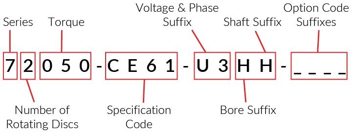
Base Models: 71010-CE61, 71015-CE61, 72025-CE61, 72035-CE61, 72050-CE61, 73050-CE61, 73075-CE61, 74075-CE61, 74105-CE61
Standard AC Voltages (single and three phase)
Suffix | Voltage
Y1 | 110/220V, 50Hz (single phase only)
11 | 115/208-230V, 60Hz (single phase only)
R1 | 115/230V, 60Hz (single phase only)
T1 or T3 | 220/440V, 60Hz
51 or 53 | 208-230/460V, 60Hz
U1 or U3 | 230/460V, 60Hz or 190/380V, 50Hz
P1 or P3 | 575V, 60Hz
Special Voltages Available
Suffix | Bore Size | Shaft Size | Keyway
HH | 1-1/8” | 1-1/8” | 1/4” x 1/8”
KK | 1-3/8” | 1-3/8” | 5/16” x 5/32”
MM | 1-5/8”* | 1-5/8” | 3/8” x 3/16”
*For brakes below 75 lb-ft torque rating that require
1-5/8” bore size, contact factory
Suffix | Description
F | Foot Mounting Bracket
H| Heavy Duty Friction Disc(s)
M | Military Marine Finish
N | Non-Military (Maritime) Marine Finish
P | Tropical Protection
R | Internal Space Heater
S | Stainless Steel Stationary Disc(s)
V | All Position Vertical Mounting
VO | Vertical Over Motor Mounting
VU | Vertical Under Motor Mounting
XS | Microswitch Warning
| Torque (lb-ft) | Model # | # of Friction Discs | Thermal Capacity (HPS/Min) | Weight (lbs) | Inertia (lb-ft2) | "C" | "X" | "AC" | "N" | Max Motor Shaft Length "AHbore" = 1-1/8 dia | Max Motor Shaft Length "AHbore" = 1-3/8 dia | Max Motor Shaft Length "AHbore" = 1-5/8 dia | Brake Shaft Length "AHext" = 1-1/8 dia | Brake Shaft Length "AHext" = 1-3/8 dia | Brake Shaft Length "AHext" = 1-5/8 dia |
|---|---|---|---|---|---|---|---|---|---|---|---|---|---|---|---|
| 10 | 71010-CE61 | 1 | 10 | 40 | 0.055 | 7.53 | 1.25 | 1.13 | 0.50 | 2.63 | 2.63 | 2.63 | 2.63 | 3.13 | 3.75 |
| 15 | 71015-CE61 | 1 | 10 | 40 | 0.055 | 7.53 | 1.25 | 1.13 | 0.50 | 2.63 | 2.63 | 2.63 | 2.63 | 3.13 | 3.75 |
| 25 | 72025-CE61 | 2 | 11 | 42 | 0.076 | 7.53 | 1.25 | 1.13 | 0.50 | 2.63 | 2.63 | 2.63 | 2.63 | 3.13 | 3.75 |
| 25 | 73025-CE61 | 3 | 12 | 49 | 0.108 | 8.10 | 1.81 | 1.69 | 0.50 | 3.13 | 3.13 | 3.13 | 2.63 | 3.13 | 3.75 |
| 35 | 72035-CE61 | 2 | 11 | 42 | 0.076 | 7.53 | 1.25 | 1.13 | 0.50 | 2.63 | 2.63 | 2.63 | 2.63 | 3.13 | 3.75 |
| 35 | 73035-CE61 | 3 | 12 | 49 | 0.108 | 8.10 | 1.81 | 1.69 | 0.50 | 3.13 | 3.13 | 3.13 | 2.63 | 3.13 | 3.75 |
| 50 | 72050-CE61 | 2 | 11 | 42 | 0.076 | 7.53 | 1.25 | 1.13 | 0.50 | 2.63 | 2.63 | 2.63 | 2.63 | 3.13 | 3.75 |
| 50 | 73050-CE61 | 3 | 12 | 49 | 0.108 | 8.10 | 1.81 | 1.69 | 0.50 | 3.13 | 3.13 | 3.13 | 2.63 | 3.13 | 3.75 |
| 50 | 74050-CE61 | 4 | 13 | 56 | 0.145 | 8.10 | 1.81 | 1.69 | 0.50 | 3.75 | 3.75 | 3.75 | 2.63 | 3.13 | 3.75 |
| 75 | 74075-CE61 | 4 | 13 | 56 | 0.145 | 8.66 | 2.38 | 2.25 | 0.50 | 3.75 | 3.75 | 3.75 | 2.63 | 3.13 | 3.75 |
| 105 | 74105-CE61 | 4 | 13 | 56 | 0.145 | 8.66 | 2.38 | 2.25 | 0.50 | 3.75 | 3.75 | 3.75 | 2.63 | 3.13 | 3.75 |
